New flow model for steam generator tube leakages developed
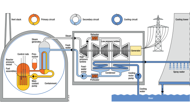
By far the most common type of reactor in the world is the pressurised water reactor (PWR). Like other reactor types, it uses the energy produced during nuclear fission by vaporising water; the steam then drives a turbine, which in turn feeds electricity into the grid via a generator – in this respect, a NPP works no differently than a conventional coal-fired power plant.
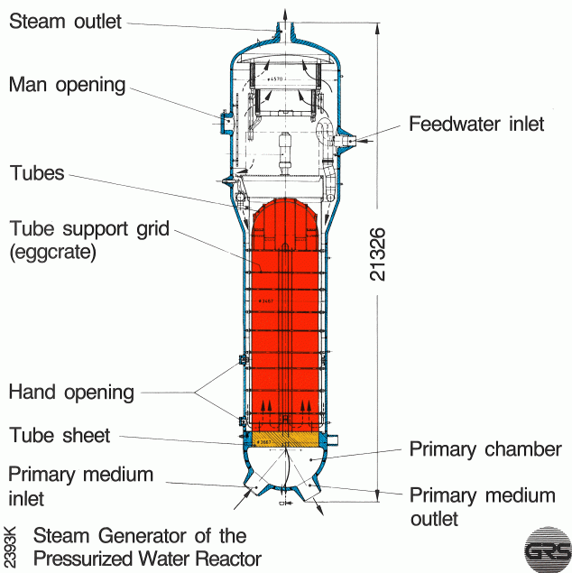
In the primary circuit, the water is passed through the reactor core where it heats up to 330 °C. Since the water is also at high pressure (up to 160 bar), it does not evaporate. Pumps convey it through pipes from the reactor core through the so-called steam generators. The steam generators in turn contain water from the secondary circuit. Since this water is at a lower pressure than the water of the primary circuit, it is heated and evaporated by the transferred heat and then fed to the turbine.
Steam generator tubes for efficient heat transfer
There is a large number of these u-shaped tubes; usually thousands of them run through a typical steam generator.
During operation, the tubes are exposed to high temperatures, large pressure differences, and vibrations caused by the flow. Especially in the outer area of the tubes (secondary side), corrosion damage due to deposits in the area of the tube sheet cannot be ruled out. These deposits are removed at regular intervals and the steam generator tubes are checked for corrosion attack. If wall thinning above a threshold value is detected, the affected tubes are sealed with plugs.
NPP operator must demonstrate that leakage events are controlled
One example of such damage is crack-like wall thinning, which has been found in various NPPs, including German ones. Should a crack go right through the tube wall, there will be a leakage. Such through-wall cracks are not classified as an accident. However, if the crack length reaches a certain extent – this is referred to as the critical crack length or critical crack – there will be very rapid crack growth, which will lead to the double-ended rupture of the affected steam generator tube in a short time.
If a leak occurs, coolant may be lost and radioactively contaminated water may leak from the (actually closed) primary circuit into the secondary circuit, and radioactivity may be released into the environment. German NPPs are designed to withstand both leakages and a double-ended rupture, which is considered a design basis accident.
This design includes the installation of leak detection systems in the NPPs that measure, among other things, the activity in the main steam (i.e. in the secondary circuit). These methods are very accurate, so that even very small leaks can be detected – however, they only provide information that a leak is present; the size of the leak area cannot yet be derived from this information. However, the leak size is the decisive factor in assessing whether a crack is critical or subcritical.
Research to determine the leak rate
But how to reliably determine the size of the leak or the length of the crack? This is where the so-called leak rate comes in. The leak rate quantifies the volume of a substance that escapes from a leak in a certain time. The idea behind it: If I know how much has escaped from a leak thanks to the activity measurements and know other parameters such as the pressure difference between the primary and secondary circuit, this allows me to mathematically derive the leak size.
However, due to the thin steam generator tube walls, established methods for leak rate determination, which predominantly apply to thick-walled structures, cannot be directly transferred to steam generator tubes. In order to be able to quantify the leak rate reliably, scientists from GRS and the Materials Testing Institute (MPA) of the University of Stuttgart have conducted in-depth studies funded by the Federal Ministry for the Environment and the Federal Ministry of Economic Affairs. The aim was to develop a flow model that reliably describes the leak rate in a steam generator tube.
In developing their flow model, the "Metastable Free Jet Model" (FJM), the GRS research team initially looked at classical leak models. Here, relevant thermodynamic variables are primarily pressure, temperature, and steam content. In a schematic diagram, the area from which the liquid flows from the tube can be divided into several small areas. These areas are described in the following paragraph.
Outflow area divided into five sections

- Primary medium: The constant conditions of the primary circuit prevail here (pressure and temperature are relatively high).
- Inflow area: In the inflow area, the pressure may already be dropping. The water is still liquid.
- Convergence area: The liquid is accelerated by the pressure drop and flows through the leak. On the outside, it reaches the external pressure but does not yet evaporate (metastable liquid phase).
- Free-jet area: Here, delayed flash evaporation sets in after some time, i.e. the liquid evaporates.
- Secondary medium: conditions in the secondary circuit prevail (pressure and temperature are lower than in the primary circuit).
The most important areas to be described mathematically are the inflow and the convergence area. As measurements and recalculations during the course of the project showed, the same conditions as in the primary circuit still prevail in the inflow area, i.e. temperature and pressure do not differ.
In order to investigate these theses and to develop and validate the Metastable Free-Jet Model (FJM), the scientists recalculated experiments from the research literature and experiments conducted specifically for this purpose at the University of Stuttgart (links to the relevant experiments are listed at the end of the text). Among other things, they found that the methods used for leak rate tests in thick-walled pipes sometimes showed larger deviations from the experimental results. With the FJM, the researchers therefore developed a description with which far more precise results can be achieved. Their model is based solely on the thermodynamic conditions (pressure, temperature, steam content, etc.). They adapted the model accordingly for the convergence range and the metastable liquid phase.
Model validated by means of experiments
In order to validate the FSM, experts from the MPA at the University of Stuttgart carried out experiments again together with the GRS research team to investigate how flows through thin-walled tubes behave and to measure the leak rates. In addition, they made video recordings showing the flow pattern in the outflow areas of the leaks. The FJM showed good agreement with the experimental results across the entire temperature range. The researchers therefore recommend including the model in the investigation and assessment of possible steam generator tube leaks.
The work on leak rate calculation for steam generator tubes was carried out with the support of the Federal Ministry for the Environment and the Federal Ministry of Economic Affairs and has not yet been completed.
Project information
GRS project: Expert advice to the BMU on scientific-technical questions regarding ad hoc problems within the framework of federal supervision according to Article 85 of the Basic Law – WP3: Validation of leak rate determination for steam generator tube leaks
Period: 09/2019–10/2020
Term: 14 months
Commissioned by: Federal Ministry for the Environment, Nature Conservation and Nuclear Safety
MPA project: Central studies and evaluation of current issues with regard to pressure-retaining components of nuclear power plants in power operation – WP1: Validation of leak rate determination for steam generator tube leaks
Commissioned by: Federal Ministry for the Environment, Nature Conservation and Nuclear Safety
GRS project: Further development of analytical methods for the assessment of the leak-before-break behaviour of metallic components including leak rate determination
Period: 02/2017–01/2020
Term: 36 months
Commissioned by: Federal Ministry of Economic Affairs and Energy
GRS project: Further development of methods for integrity and reliability assessments of pipes
Period: 03/2020–02/2023
Term: 36 months
Commissioned by: Federal Ministry of Economic Affairs and Energy

